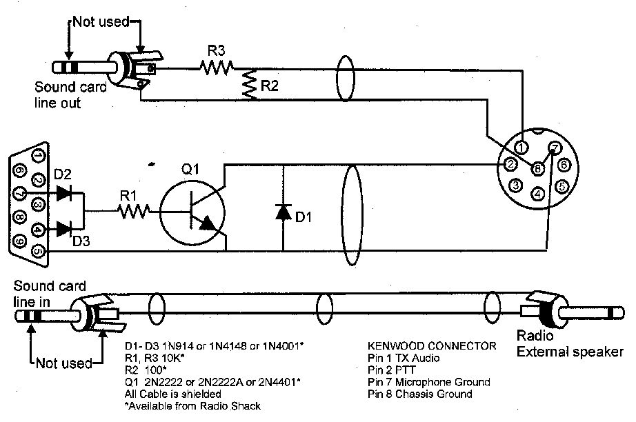
When I first discovered PSK radios needed an interface, or at least mine did and still do.
At the time there were some very nice commercially made interfaces, and at the same time the internet was full of schematics for making your own with a few diodes, resistors and transistors, most if not all of the needed items could be purchased at your local Radio Shack store.

Click image to enlarge
Back in 1999 computers had a 9 pin serial port (desktop and laptops) and very few had USB ports. But as time marched on and my computers were upgraded there came a point in time when the 9 pin serial port was dropped from computers. At that time I purchased a USB to Serial Adaptor, and for the most part that worked.
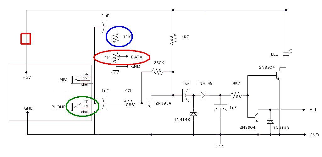
But I was not happy with the extra connection and extra wire so I started looking again for an interface and during my search I found this website http://www.g4ilo.com/usblink.html G4ILO SILENT KEY October 24, 2014. With Julian's permission (he said I did not need it but as grateful for me asking) I built a new interface based on his info. I made some modifications based on my needs at the time.
I built the PPT circuit on a piece of perf board and ran wires as needed to connect the components on the board. I also made some modifications as I built it, see the image below.
- At the red square I added a spst toggle switch to turn off the PPT circuit.
- At the red circle I changed out the 1K resistor to a 1K pot
This is used as a control for the output of the audio. I use the pot (which is on the front to the interface box) along with an adjustment within the Fldigi program. The pot lets me make adjustments without getting into the sound card settings in the computer which I have set at levels that work with my set up. I have the speaker setting at 20% in the computer.
- At the green circle I put a spst toggle so that I can tie the tip and the ring (right and left channels) together. By applying a constant tone via the Fldigi program on the right channel the ppt circuit is kept active between words and the radio does not try to cycle between TX and RX. I should have just tied these two together and left out the switch, I always use the tone from the Fldigi program.
- At the blue circle I put a spst toggle parallel to the 10K resistor thinking that if I need to boost the output audio level I can.
I always leave it the non bypass setting. DON'T need it. NEVER use it. If I did use it, it would cause a lot of splatter and we don't want splatter now do we.
- Other modifications I made were
- added a red LED in to the PPT circuit after the switch at the red square. This LED is lit when the PPT circuit has power (switch is in on position)
- added a pot (I believe it is a 10K) to the mic side of the sound card. This provides adjustments to the input. This was added later.

Click image to enlarge
Here is an example of what the circuit board can look like.
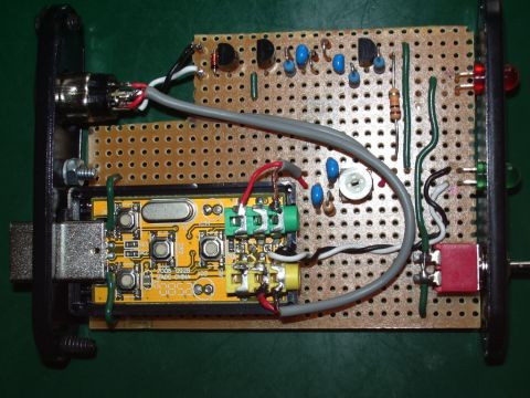
Image provide by http://www.g4ilo.com/usblink.html |